|
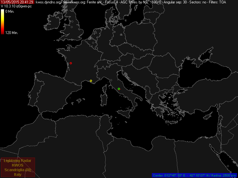
RDF -
stand-alone receiver (the
range will change to the closer storm - the strokes are
superimposed to the MSG-Rapid Scan Service image - UTC)

[click on the image to see the animation] |
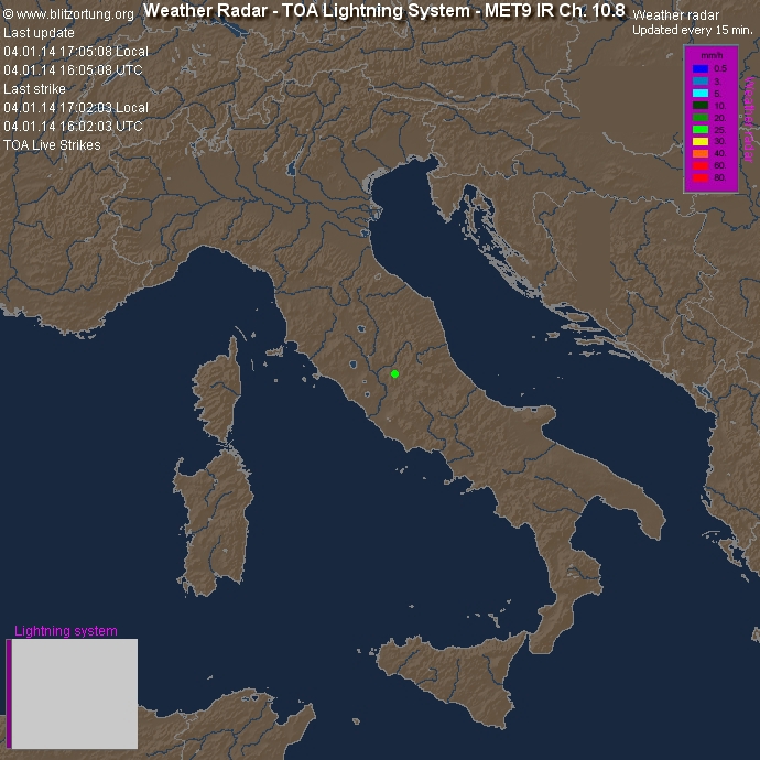
KWOS RDF stand-alone lightning detector is used with
NexStorm for data coordination with
StrikeStar Europe.
StrikeStar EU data is then processed and combined by
the WASP2 prog to provide a local area image upload
every 5 mins.

[click on the image to see the animation] |